 Grainge and Hodder have been advertising in the modelling press and make their modular board kits available via ebay. Established in 1977 as a photo etching business, they have embraced the modern technology of laser cutting to augment their range. Continue reading Grainge & Hodder Baseboards
Tag Archives: Straight Board
Transit board modifications
To transport the module boards safely, I made some transit boards out of off-cuts of 12mm MDF. These were always going to be a Mark 1 version, consisting simply of a square with a line of holes drilled to match those on the interface plate on opposite faces and a hand hole in the middle.
These worked, and well, holding the boards a small distance apart and making them easy to load. However, very quickly two limitations were noticed.
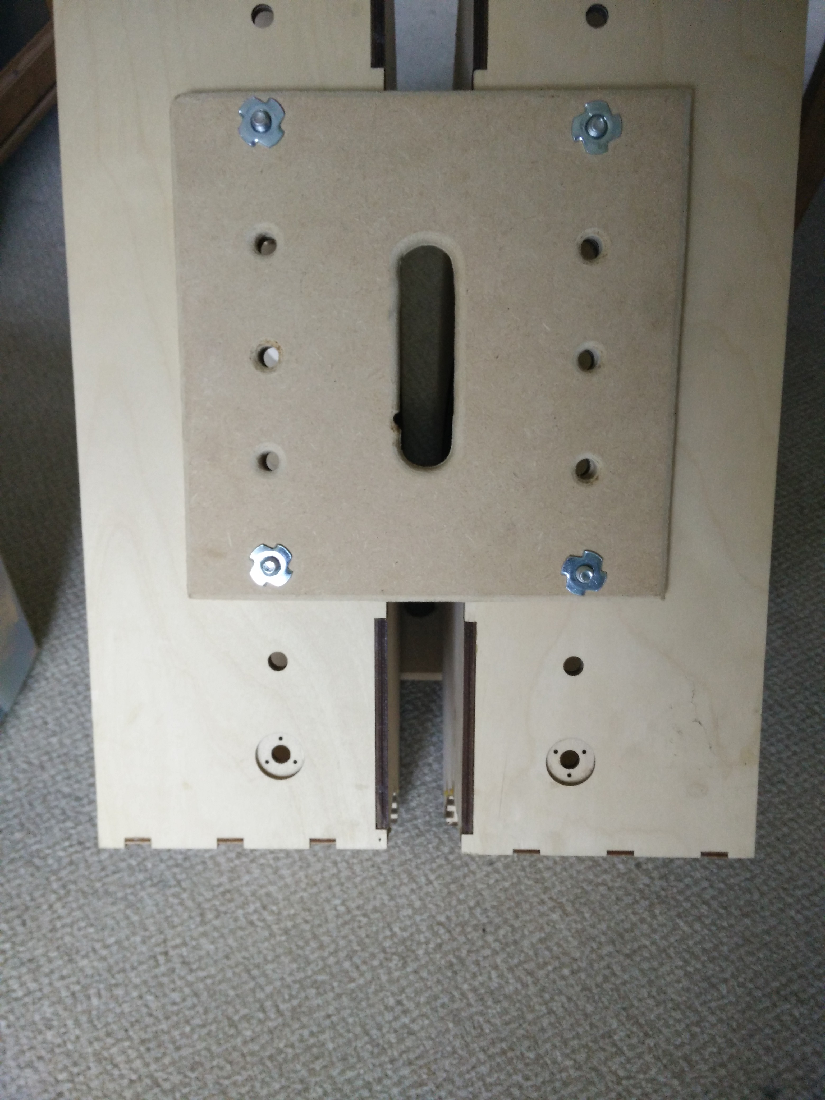
Firstly, the hand holes are all but useless, because the boards are held so close together that there’s nothing for your fingers to grab hold of anything. However, I don’t intend to do anything about that, because these are Mark 1 and were going to be replaced later with newer ones out of thinner ply.
And that was the other weakness. The 12mm MDF meant that the bolts, when used with two washers to protect the wood, were difficult to engage the wing nuts and, when done up, only just picked up enough threads to be secure. The solution was simple; embed tee nuts into the transit boards. It works a treat, but is still Mark 1.
First test run
Have I mentioned that it’s only two weeks until the first showing of our modular layout at the Seaboard Southern Annual Exhibition at Horsham? Having progressed to the point of electrical continuity, it was felt that a full test was long overdue.
So the car was loaded, two straights and two corners crated together together with five sets of legs were all loaded into the boot of the car and carted off to Caterham for a trial run with Brian’s modules and fiddle yards.
Setting up on the deck outside the shed was very quick, especially as Brian had already set up one fiddle yard and his two boards. We added my four in as straight a configuration as could be managed with two corners, and added have of his other fiddle yard on the other end. Sadly, the deck wasn’t long enough for a full test but Brian had already confirmed full functionality of his complete set.
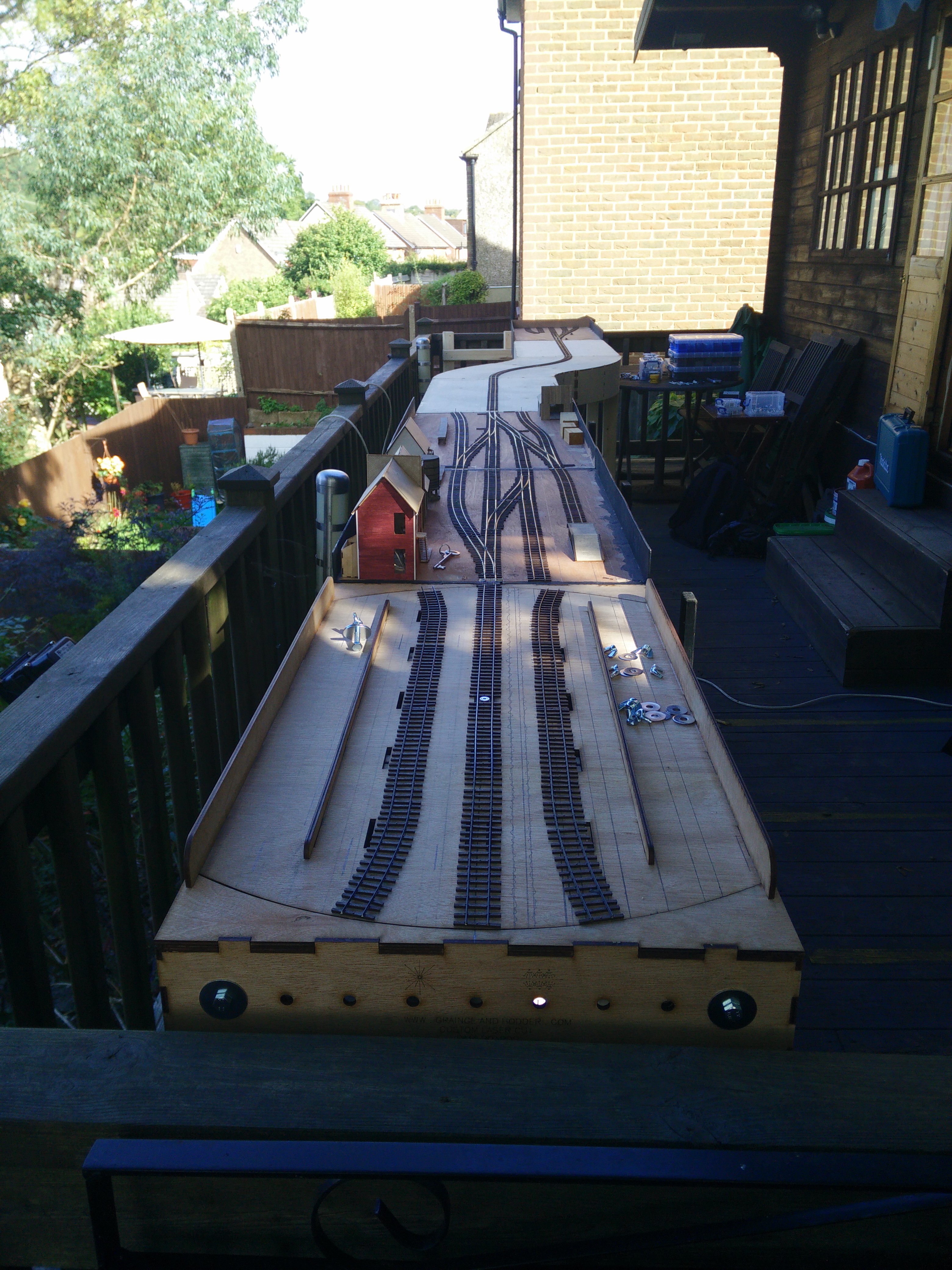
Having plugged everything together it was all looking good, until the locomotive on the first train crossed the joint between Brian’s boards and mine, stopping dead with that annoying ticking from the command station notifying a short circuit. Thankfully, it was very easy to spot – I’d managed to get the plugs and sockets the wrong way round.
Sorting it was equally easy. Swapping the plug and socket on each end of my four module stretch confirmed that to be the problem and the train proceeded to the far end of the layout. Five minutes later and all of my plugs and sockets had been swapped so that, whichever of us was wrong, we are now at least the same!
All in all, the test was an outstanding success. It was pleasing to see how quickly the layout went together, and came apart again. That it worked almost straight out of the box was a bonus. We’re ready for the exhibition in two weeks, which is a huge relief to me at least. No electrical or mechanical changes will be made now!
Testing for continuity
Have made up all the jumper cables the other evening, the last remaining electrical job was to solder the dropper cables on the corner boards. These hadn’t been done because I wasn’t happy with the track alignment. However, with the first exhibition looming …
I’m still not happy with the alignment of the track, because it’s not centred exactly. However, to do it to my satisfaction, I need to invest in a Code 83 roller gauge and construct a jig to ensure the accurate centring of the track at the ends of any board. That ain’t gonna happen before the Seaboard Southern exhibition, so it stays as is.
All that said, the boards were laid loosely on the floor and plugged but not bolted together. The connectors at the far end were plugged together as well, to create a ring main, and the connectivity tested. The resistance dropping from infinity proved that current was flowing the whole way round. Result!
Making the Jumpers
After another long hiatus, and with the Seaboard Southern Show now only a few weeks away, I sat down this evening with a film on Amazon Prime, two rolls of cable, a bunch of banana plugs and sockets plus some chocolate blocks and proceeded to make up the jumper cables for connecting power to adjacent boards.
 Here’s the work area and tools laid out, with three cables already made up. It’s not a big tool kit for this job; ruler, cutters, strippers and screwdriver.
The cutting mat is just to keep the tools up together, rather than spreading them around the entire floor as I work!
Each board requires one plug and one socket each in red and black, so I’ve got four full sets to make up.
 I jury-rigged a cable reel as well, to stop the two large spools rolling around the room. You might recognise the IKEA Komplement shoe rack from their Pax wardrobe range!
The folding wooden ruler is ideal for jobs like this, as it’s heavy and sturdy enough to remain where it’s placed.
There’s a lot of jumper cables left on those spools, as I bought 100m of each!


Here’s the basic process of making up each wire. This process was repeated four times for each of the four boards, so 16 cables in total.
Tomorrow’s job is to solder them to the boards.
wiring updates for the FremOn30 boards July 2015
Not the most interesting sides to the hobby but one I do enjoy. 3 boards are now mainly finished apart from some point wiring to feed the frogs or cross vee’s.

This is one of the main depot boards. seen in this picture are the 5 point motors and the DCC sub districts. also seen on the right are the two point controllers.

This is the second depot board with the DCC bus lines and point motors fitted

This shows the tree boards that are complete. The board top right is the main fiddle yard board with just 5 plain tracks. I have wired both ends of each track for belt and braces. it will take 2 wires to be disconnected before a track will lose power.
The forth board is awaiting points from the USA, but the guy is ill and I may have to think about only having 3 tracks working for the first show.

To this end I had a play with hand point throws on the baseboard, they will allow me to control the points but the frog will be dead.

The last job i have done is add adjustable feet to the bottom of the legs. this should allow for any uneven floors at shows
Track and Wiring
Progress on the modules has been slow, for which read non-existent. With the looming date of the Seaboard Southern show in September, at which these are expected to not only appear but be operational, it’s high time to extract the digit!
A sunny Saturday afternoon with fellow moduler Brian Daly saw:
 feeder droppers added to two yard lengths of Micro Engineering Code 83 0n30 flexible track
- said track pinned to the boards and soldered to the Gapmaster GM006 units used as end ties
- droppers on the straight boards soldered to the slug tape on the underside
- alignment tested by bolting boards together in various orders and running a skeleton log car
I’ve still got to add droppers to the curved boards and, having had some fun with the alignment, I think I’m going to make a jig for centring the track, just for my own sanity. The fact is that my eyeballs are rubbish at measuring!
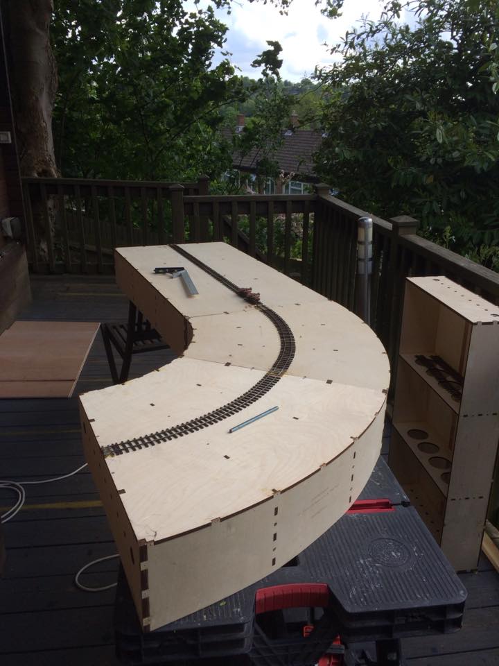 Here you can see the two 45° boards and one straight all bolted up together, with the other straight board standing on its end to the right.
The flowing line of the track can clearly be seen. Module standards discourage connecting the two corners reversed without a straight between them.
Before paint is applied, I think I’m going to put the supplied 3mm plywood fascias on, if only to hide the finger joints and screw holes.
Then it’s time for some scenery!
Fremon30 boards 3 and 4
Tonight I set up boards 3 and 4. These will have a small depot with a couple of loops and sidings. Trouble is I cannot decide about the track plan.


Which one one do you like
1
2
3
4
Fremon30 boards update
This afternoon I worked on the first two boards for the modular layout.

This is is the first board with the gapmasters been glued in place.
what cannot be clearly seen is that all the tracks and clearances are marked on the board.

The centre track in place.

The second track in place. This hasn’t got gap masters at the ends. I will use normal copper clad sleepers.
 The third track fitted, that’s one side down. Ply fascia still to add to this board and the next one.

The fourth track is added. The gap between tracks is the maximum loading gauge and is set using a standard on30 loading gauge.

Thats the the fifth and final track added. I have pre drilled holes for each rail 75mm in from each end. This will allow each rail to be connected twice to the DCC bus line fitted to the underneath .
To make the rails straight I used a long spirit level.

The second board was then added and the markings carried across. Gapmasters were added to the centre line track.

The he first point was then added and tracks linked up. The centre track is not fitted, just laid into rough position. I will need to order the three way point and may need to build a short extension board for this all to fit.

A good afternoons work. Hopefully I have enough turnouts and track to do the other 2 modules. I will check this one evening this week.
FremOn30 modular boards
More work done on the FremOn30 modular layout boards.
1 board is complete with side fascia’s
1 board is complete waiting side fascia’s
2 boards end trim to cut and fascia’s to add

One set of end boards is made and one pair of boards are now boxed.

All boards have copper tape added for the DCC bus for track and another DCC bus for accessory’s

Tim Horn Laser Cut Boards
 When the idea of Frem0n30 was first discussed among us, we approached Tim Horn and asked him to adapt some of his existing laser-cut baseboard kits to accommodate the Frem0n30 interface standard. Continue reading Tim Horn Laser Cut Boards